Testing & Replacing Your SolenoidI'd been carting around town a while back, and pulled into my driveway and stopped in the CartCave. As always, I plugged in the charger and went in the house. The next day I unplugged the charger, climbed in the cart and turned on the key, and pushed the pedal to the floor. And nothing happened. It didn't move... it didn't even make a noise. I tested all six, 6-volt batteries (I have a 36-volt system) and they all clocked in at between six and seven volts. I then put the meter probes on the battery series endpoints, and hit over the 36-volt level. At that point I had a pretty good feeling that the problem wasn't with the batteries, so I then looked to the solenoid. It's not all that uncommon for a solenoid to go out, and they're relatively easy to test. I should say up front that I first found the solenoid test procedure on the D&D Motor Systems webpage, and it contains a ton of of information on solenoids. I believe in giving credit where credit is due!
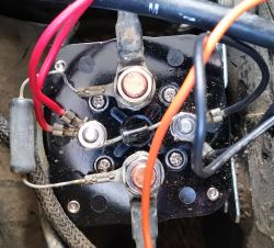
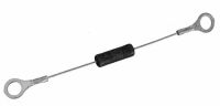
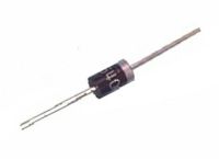
1. With all the prep work done, let's get serious. Remove the screws and disconnect the cables from the two large posts. As you do, wrap the cable ends in electrical tape as you disconnect them. In my opinion, you can never be "too safe," so please take precautions. Once that's done, reconnect the wire from the battery series that you disconnected above (in my case, between batteries three and four). Be careful, because you have current to the solenoid through the smaller posts. Get out your voltmeter, and it's time to begin. Make sure that the ignition key is off, and that your golf cart directional switch is in the neutral position. Set the voltmeter to measure ohms, and put a probe on each large post. There shouldn't be a reading at this point. 2. Next put the golf cart directional switch to forward, turn on the key, and press the acceleration pedal. There should be an audible "click" from the solenoid. If you hear it, continue to step #3. If not, go to step #4. 3. You're here because you heard a click from the solenoid in the last step. With your voltmeter still set for ohms, put a probe on each large post again, and repeat step 2. The reading should be in the range of 0.0 to 0.4 ohms. If it's higher than that, then the solenoid has faulty contacts and you're going to need to replace it, so go to step #5. Otherwise, the problem is somewhere else, not in the solenoid. Re-connect everything and keep troubleshooting. 4. You're here because you did not hear a click from the solenoid in step #2. Set your voltmeter to measure DC volts (200 scale), and this time put a probe on each of the small posts, and repeat step 2. If the meter indicates full battery voltage for your cart, but there is still no click, the coil inside the unit is faulty, and you're going to need to replace the solenoid, so go to step #5. If the meter remains at zero, the problem is somewhere else, not in the solenoid. Re-connect everything and keep troubleshooting. 5. If you must replace the solenoid, go online and do a web search for one for your golf cart make, model, and voltage. For example, in my case I was looking for one for an EZ-GO TXT 36-volt system. There should be a photo of it online, and compare it to the one in your cart to make sure that it's the same one. Most places have a turnaround time of only a few days from ordering. Once you have the new one in hand, it's simply a matter of disconnecting a wire between two of the batteries in the series to break up the flow of electricity, and then moving the wires from the old one to the corresponding posts on the new one. Once that's done, reconnect the battery wire that you removed, and you should be good to go. Congrats - you've diagnosed and replaced your solenoid! NOTE: On mine, which is in the photo above, you'll notice a resistor connected between the two small posts, and a diode connected between the two large posts. I put these back when installing the new solenoid, but had no idea what they were used for. Yours may or not have them. After a little research, here's what I found...
Closing the contactor without a pre-charge resistor causes arcing on the contact surface and they can become pitted. Plain copper contacts experience the worst pitting and wear because that cannot tolerate peak inrush currents. Excessive pitting over time causes the contacts to weld together or not make a good contact. The pre-charge circuit draws little or no power. Its purpose is to maintain the capacitors within the controller at the battery pack voltage so that when the contactor closes, no arcing occurs. Resistor value is determined by battery pack voltage.
Happy carting, |